Description
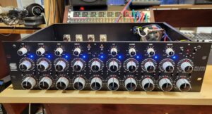
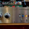
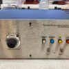
Description of the Assembled unit in stock currently:
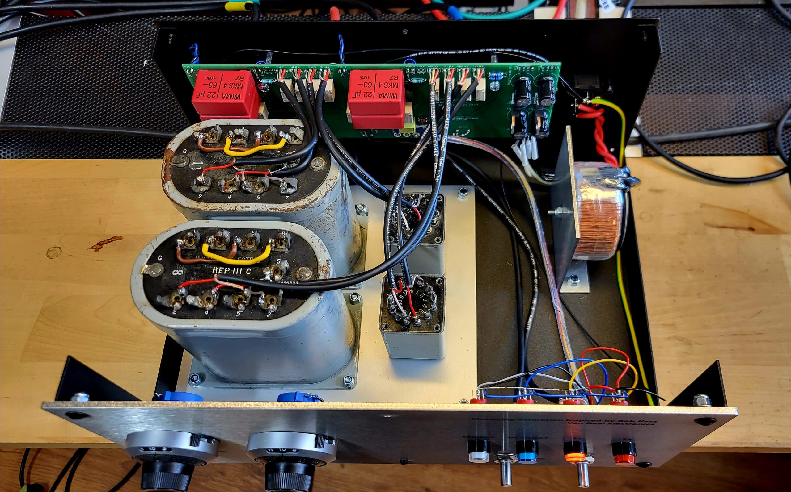
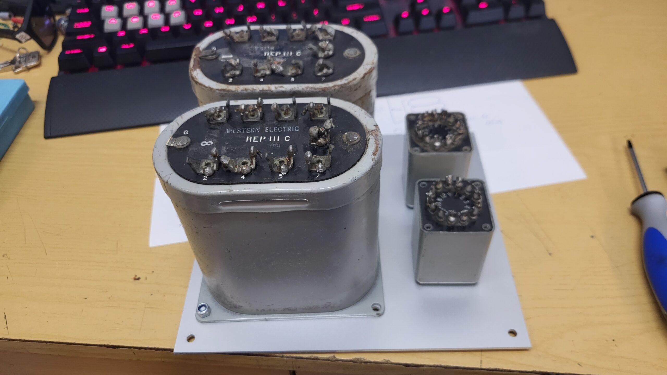
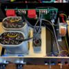
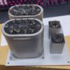
T1 transformer in that unit is UTC LS-30 repeat coil. Its big, it was made for the same purpose as the REP 111c, 1:1 repeat coil. But its not as characterless as the REP 111C. It has a bit more and it takes pushing abit more interesting than the Rep 111C.
T2 transformer is the same UTC A-20.
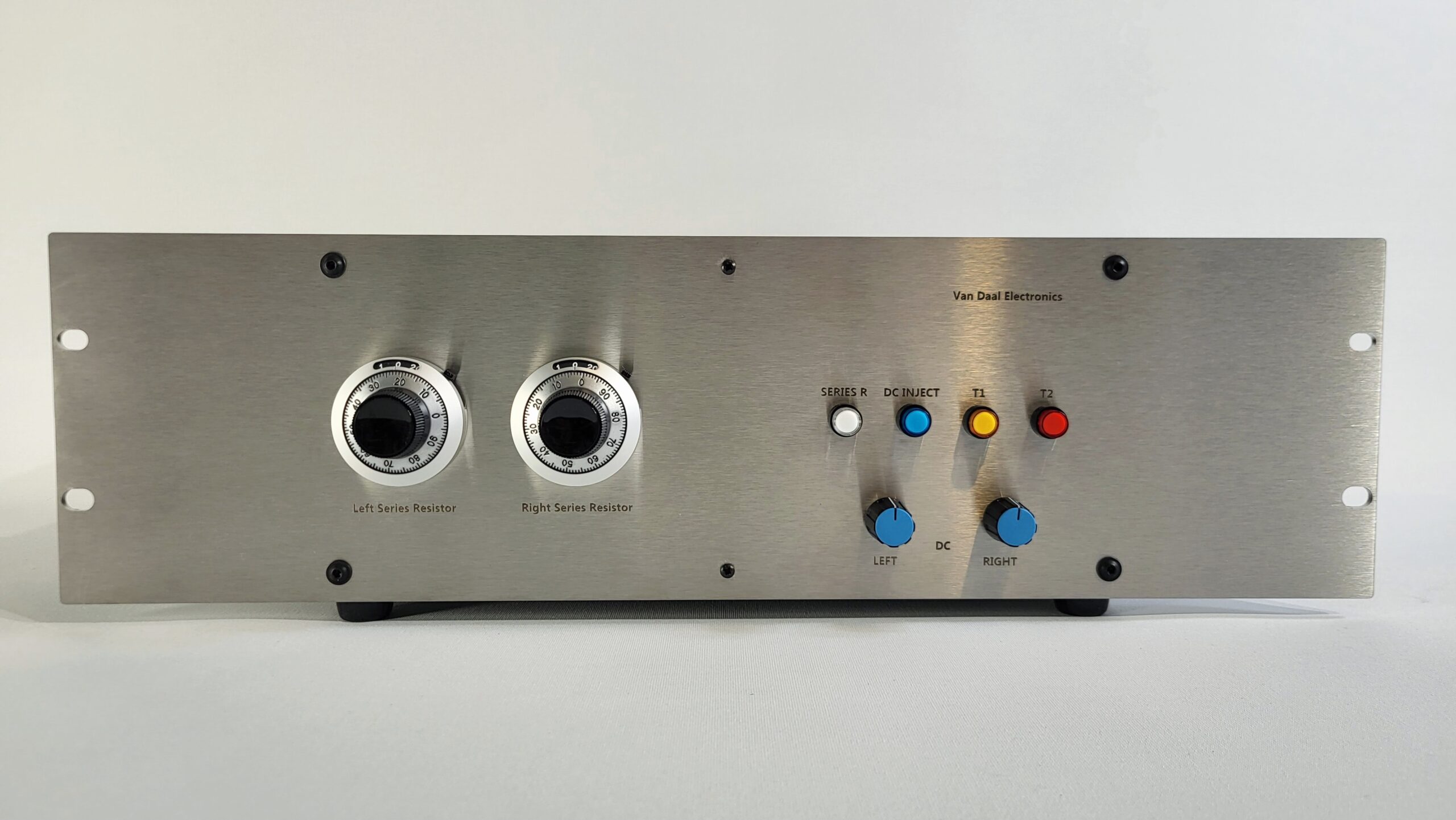
This is our take on Bob Katz Mastering Saturation unit.
This saturation unit is passive. There are no amplification stages or semiconductors in the signal chain.
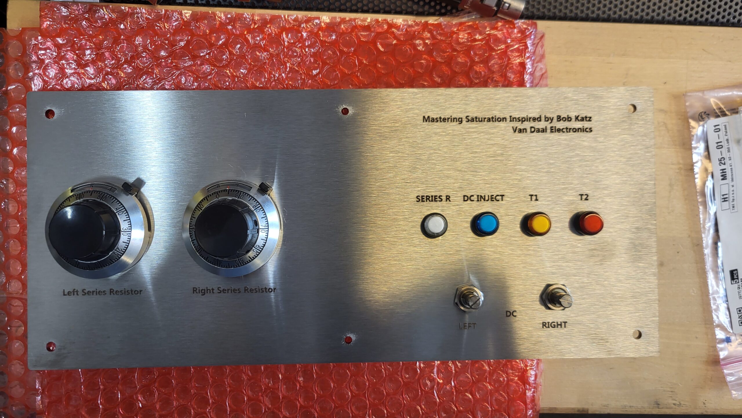
Saturation is generated by adjustable parasitic resistance, adjustable DC injection that causes transformer hysteresis.
Hysteresis is causing the transformer to colour and distort the sound.
There are 3 options
1. Full assembled. This unit comes with WE REP 111C transformers in T1 postion and UTC A-20 transformers in T2 position.
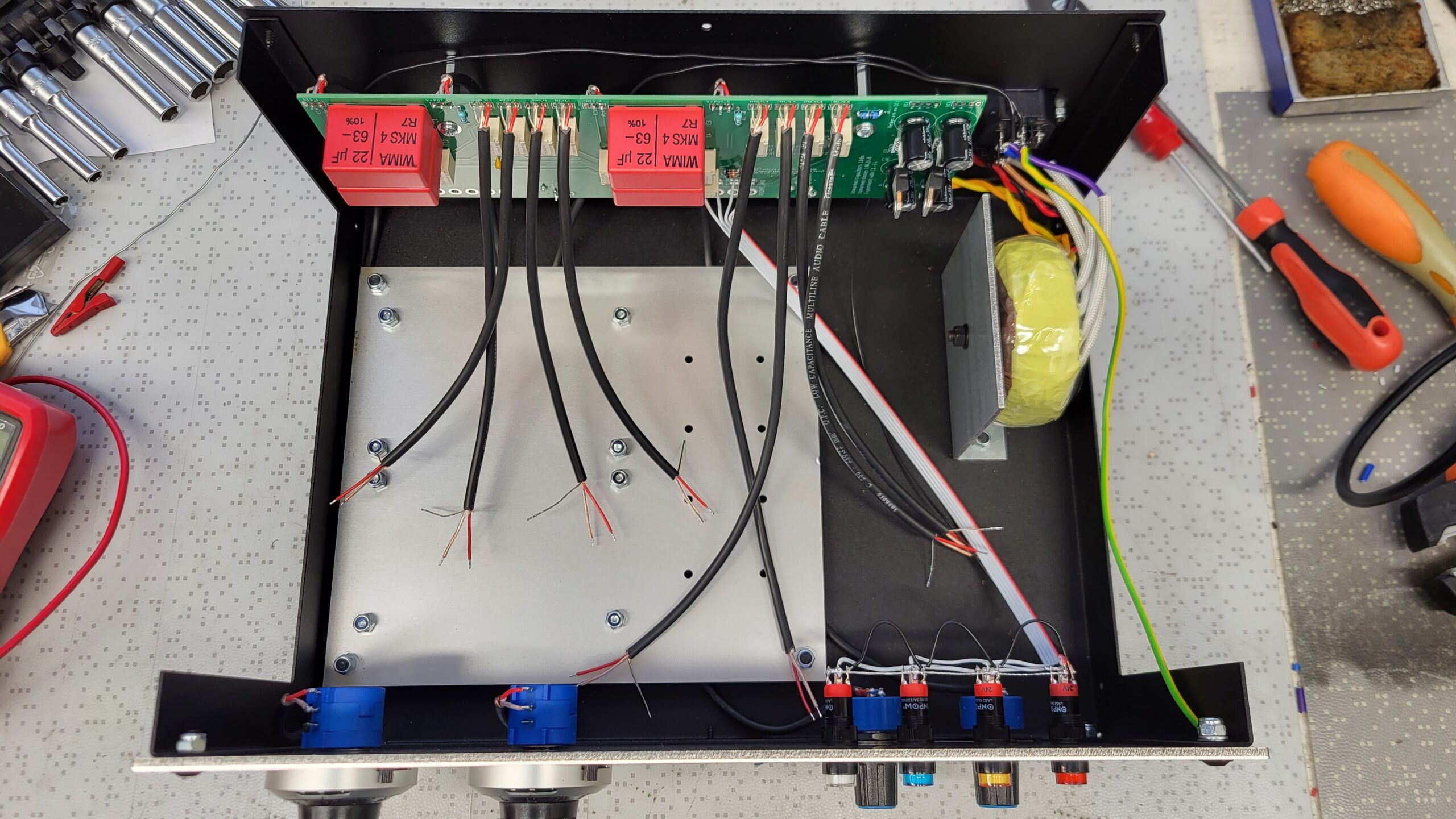
2. Partly assembled. This option comes with all the electronics and wires in, but is missing all the signal transformers.
3. KIT. This option comes with bare PCB, metal enclosure and screws to put the unit together.
**Partly Assembled option will provide you a unit that has no signal transformers inside.
Signal transformers can be selected to taste. In Bobs build, he used 2x WE REP 111C and 2x UTC A-20. Ebay is probably the easiest place to get them. You can also try other 1:1 transformers and test.
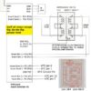
Parts can be sourced according to this BOM.
Wiring instructions to our PCB.
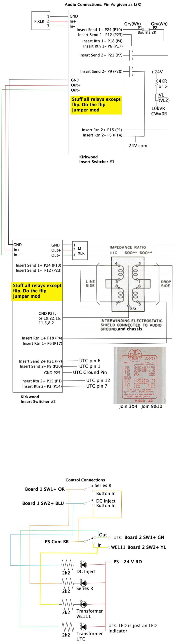
Bob Katz posted a schematic for his unit to his facebook page and this can be found here.
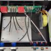
What we changed:
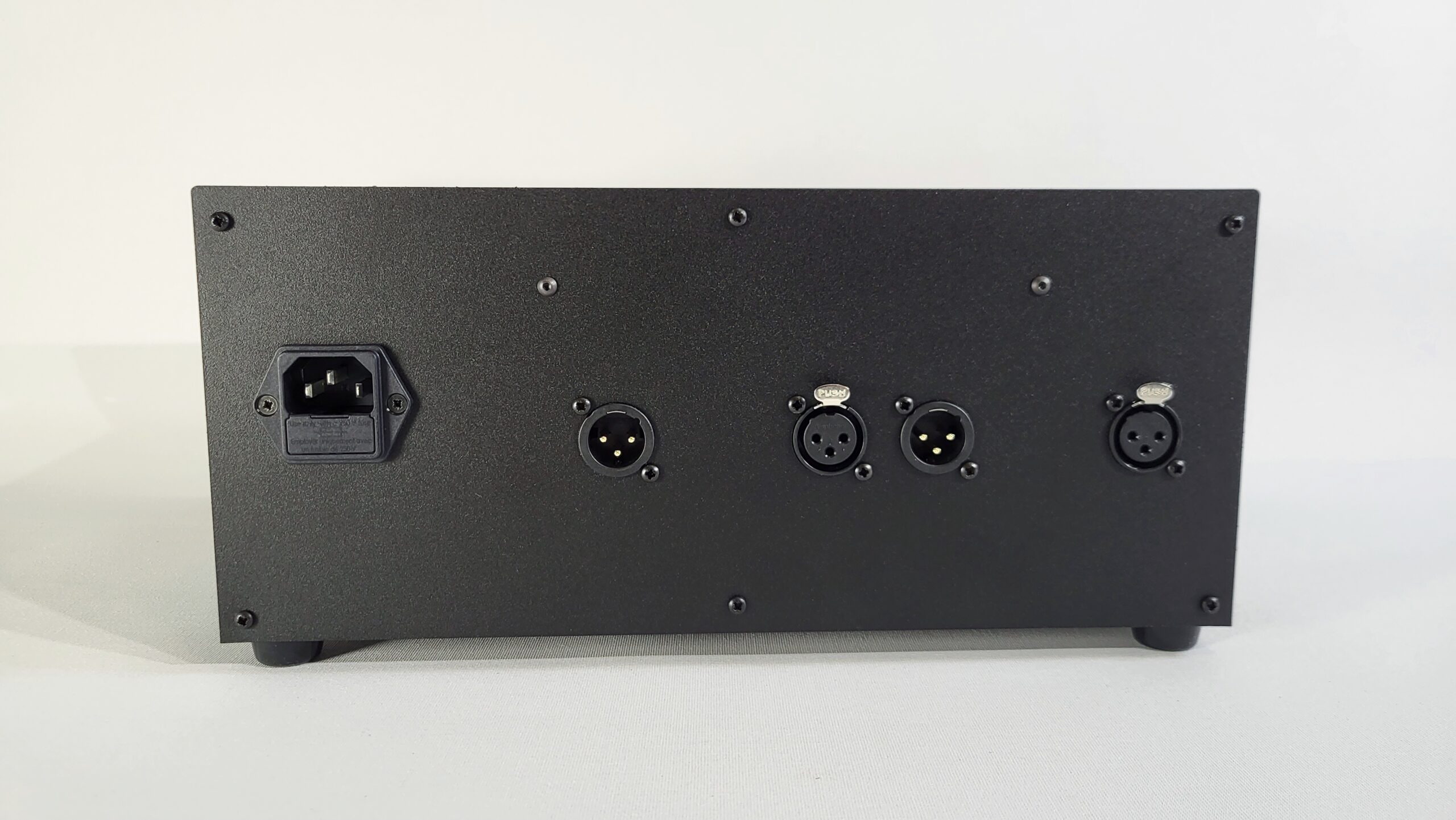
1) DC injection is feeding 24V to your signal path, without a transformer engaged can lead to damage to your soundcard. We use a relay to turn off DC injection when T1 or T2 is not in use.
2) Dedicated PCB was designed to make wiring easy and clean.
3) We use linear regulated powersupply.
4) Case is made of steel and stainless steel.
5) Transformer mounting plate is made of aluminium so that other transformers can be mounted. Its easy to drill extra holes into aluminium if needed.
6) L bracket is used for toroid transformer mounting. This is turning the magnetic field away from the signal transformers.
Some notes on the assembly.
1) Populate the PCB first, except the XLR connectors.
2) Mount the XLR connectors to the rear panel.
3) Mount the M3x25mm spacers (2pcs) to the rear panel.
4) Mount the PCB assembly on to the rear panel. Install 2 screws.
5) Solder the XLR connectors lastly when everything is well.
6) Use only shielded cables for pots and transformers.
7) XLR in Pin 1 should be wired to Mains connector ground.
8) Mains connector ground pin needs to be wired to chassis. We use frontpanel bolt as the connection point.
9) Use good quality and same model capacitors in C1-C4.
10) Signal transformers go in last, when everything is ready and tested.