After building few G9 preamps on the Gyraf PCBs it became clear that this project needs a re-design and the current state is not very DIY friendly if you aim for quality.
This is our take and contribution to the G9 full tube preamp design. You can build your own killer preamp without diving into lots of forum threads and modifications.
Build it very straight forward and easy to follow.
Electronics:
Our G9 preamp design is built on 3 different PCB board, total of 5 separate PCBs.
1. The PSU 1x
2. The preamp 2x
3. Front panel switches. 2x
The goal was to separate everything as much as possible. So all the PSU related parts are in one region of the case.
Channels are on separate PCBs for very low crosstalk.
You dont need to cut any pcbs and dont have to mess with the nasty pcb dust hazard. (like with the original design)
Pcbs are dual layer, this should result with a better shielding and shorter traces between parts.
Capacitor footprints are made for WIMA capacitors, there are are no optional sizes printed on the boards, you need to bend legs if you want to use some other sizes.
We have removed the Lundahl transformers from our design as I didnt hear or feel that the unit benefits anything. OEP transformers give very good freq response. Lundahls in this unit lack the bottom end and are dull on the upper freq. Also they are a lot more expensive. We have compared every possible configuration of lundahls and OEP transformers and made sweeps to analyze the frequenzy response curves. Set of OEP transformers really make it better by ear and on the paper.
PCBs have all the part values and numbers clearly marked with white silkscreen print.
PSU section has extensive fusing to keep parts safe. So 2 fuses on the input. Fuses between the transformers in case one should fail. Fuses for all the regulator inputs – but not for outputs.
All the voltages running to preamp boards are DC, no AC is sent to remove humm.
BOM.
There is a dedicated BOM with comments and descriptions to source all the needed parts.
The Case.
A ready to use 19″ 2U case designed for G9. Case is made of zinc coated steel.
Case is powder painted matte black and front panel screenptinted with white.
3mm front panel.
1mm rear assembly.
There is a distinctive wall inside the case that acts as a separator/shielding between the audio and power supply.
That wall also acts as a cooling profile for the voltage regulators.
All the holes are pre-lasercut so no drilling is needed except if you need to make some holes bigger if you use different parts.
Frontpanel controls.
GAIN: Rotary switch with 11 steps.
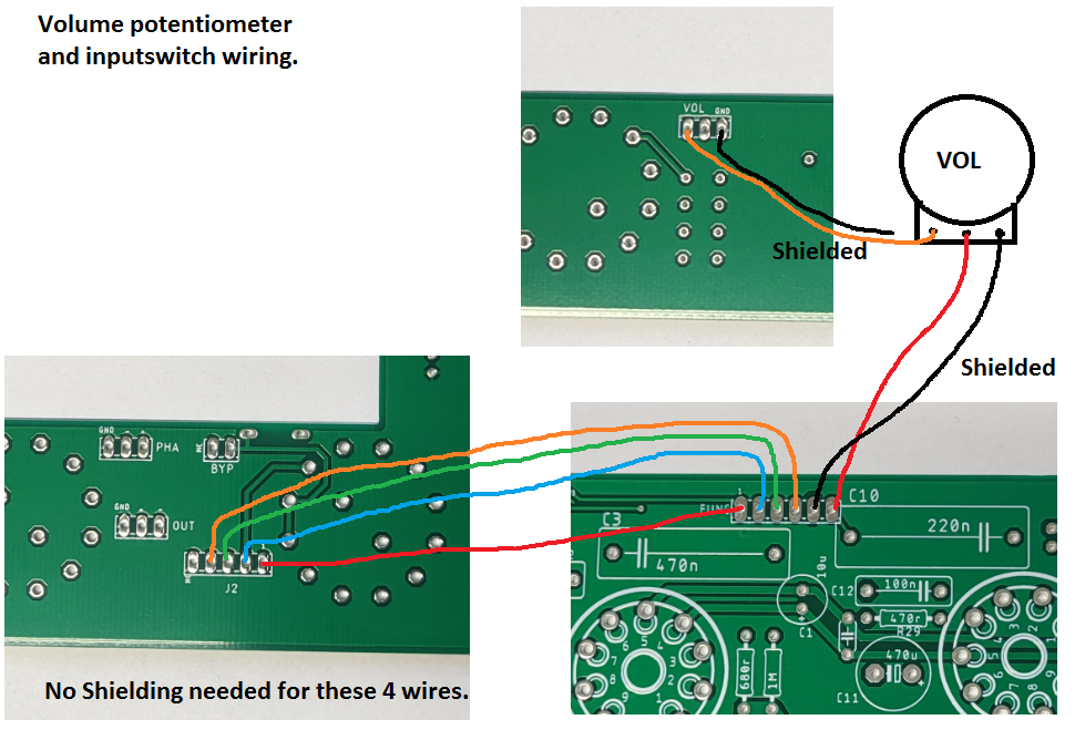
OUTPUT: Rotary potentiometer.
INPUT; PHASE; LOW-CUT: Rotary switches.
Noise.
Noise figures in this kind of design were measured to -102dB self noise (at 50Hz as its the dominant peak). That was +3dB on our setup as our converter selfnoise level was around -105dB mark. Self noise is measured with nothing connected to the preamp, with preamp gain minimum and output volume maxed out. Once you start adding more gain the noise floor is rising. The unit can do about +60dB with max gain, max volume, signal to MIC input.
Tools and materials that will come useful in this project:
1. Gauged Wire stripper. We love the pipe shaped strippers on shielded cables. Very easy to work with
2. Good shielded cable, 2 conductors + shielding. You can use regular mic cable here also.
3. TO220 insulator washers. They come handy on all M3 bolt applications where insulation is at risk.
4. Screw drivers
5. Hex socket set.
6. Soldering station.
7. Solder. 1mm Sn60Pb40 with rosin core flux.
8. Soldering flux paste. We use syringe with fine tip to apply.
9. PCB soldering frame.
10. Digital or analog multimeter. You to measure upto 400VDC, precision is not so important.
Notes:
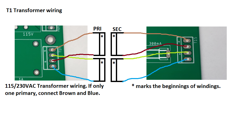
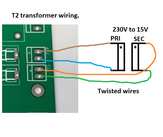
1) There are 2 power transformers used in this project. First is used to convert your grid voltage to 15VAC. Second transformer is used to convert 15VAC to high voltage for tubes. This removes the need for special transformers and regular off the shelf parts can be used.
2) Populate the boards so that the smallest parts are first and larger parts later.
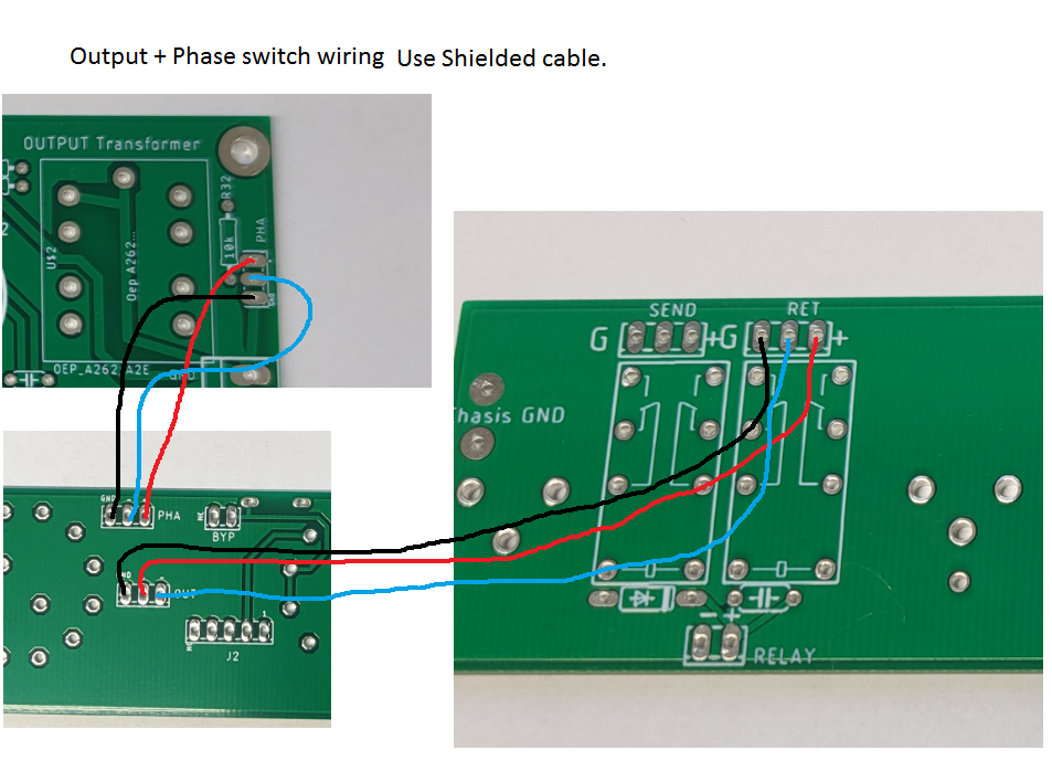
3) Shielded cables should be stripped unshielded as little as possible. Keep them as short as possible but long enough to take out boards.
4) Use the OEP transformer cans, it will make a big difference. Solder it around the transformer and use flux. Clean flux after soldering, its corrosive.
5) This unit has HIGH VOLTAGES inside. Never solder or touch parts if power is connected, always disconnect power if making changes.
6) Voltage regulators need to be insulated from the cooling profile! Use insulation pads and washers designed for TO220 transistors.
7) Fuse ratings dont mean they will work as a switch when current ratings are exceeded. They are there to be a weak sport when failure occures to save other parts.
8) When you are soldering, give the solder and parts time to heat up. You are not in a hurry. Use what ever solder you are used to. Sn60Pb40 rosin core is the easyest to work with.
9) Ground loops!! Your XLR connectors must be grounded through pin 1 on XLR connector and that ground must come from Chasis ground, not audio ground. In this unit the input XLR PIN 1 is tied to chasis ground. Read about ground loops, there are many articles. They will explain you more what is happening and why. A good thing to master!
10) Internal cable shielding is also sensitive to ground loops. Cut the shielding at the right end after assembly.